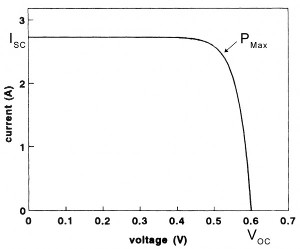
IV characteristics for a single photovoltaic cell. A solar panel is little more than a number of these in series.
A photovoltaic panel produces a voltage across its terminals which falls with increasing current draw, becoming zero at maximum current. It follows that there must be an optimal voltage at which power is maximised, somewhere in between zero and the open circuit voltage.
Tracking this power point requires constant computation, and a DC-DC converter to match source to load - the load being typically a battery, though there are exceptions. This function can be performed as part of an MPPT charge controller, or in a module attached to either each panel or to a string of panels. This technology is commercially established, but can by expensive. The most affordable commercial offering may be the "Solar Edge 300W Power Optimiser MC4," available at time of writing for £37+VAT for a 300W model. This is approximately 12% the cost of 300W of panels. These commercial offerings also utilise proprietary designs and algorithms that are difficult to assess or to repair.
To address these issues I have designed an open-hardware power optimiser which uses only readily-available, low cost parts and may be freely built or modified without restriction. It is designed for very small scale (<=200W) installations, as are commonplace on boats, mobile homes and very remote locations. In cost terms it is little cheaper than a commercial offering, but is much easier to repair and perfect for hobbyists who wish to build their own equipment. It is also ideal for slightly unconventional applications such as solar pumps or thermal-storage heaters, as it does not require a battery.
I must stress that this is not revolutionary new technology: It's simply MPPT, but adapted into a design that any hobbyist can build for a low cost and maintain cheaply. A commercial product may well perform better, but it will also be inflexible and usually more expensive.
There are several models used to calculate the electronic performance of a photovoltaic panel, but none of these capture the full behavior. A photovoltaic panel is often thought of as a current source: Drawing more current from a panel will not cause the voltage to drop far below the open-circuit voltage up until a certain point, after which the panel voltage drops sharply as current increases - a clearly non-linear relationship. The open circuit voltage, closed circuit current and optimal power point voltage are all highly dynamic - they will vary in a complex relationship with light level, temperature, shading and panel age, often changing suddenly as cloud cover partially obstructs then reveals direct sunlight. As a general rule, the maximum power point for a '12V' panel is 16V, +-4V, if correctly positioned facing the sun and without clouds. The '12V' label on these panels is not a specification for output voltage, but of the battery it is designed to be used with and a guarantee it will produce sufficient voltage to charge a 12V battery (albeit slowly) in overcast conditions.
Connecting the panel directly to the battery, however, will mean it operates at the battery voltage - around 13V for a lead-acid, the most commonly used type for small scale solar power installations. As the current the cell can produce is little higher at 13V than it is at the optimal 16V, it can be calculated that a panel connected directly to charge a battery or using a PWM charge controller will operate at approximately 13V/16V=81% efficiency - subject to considerable variation between panels and according to conditions.
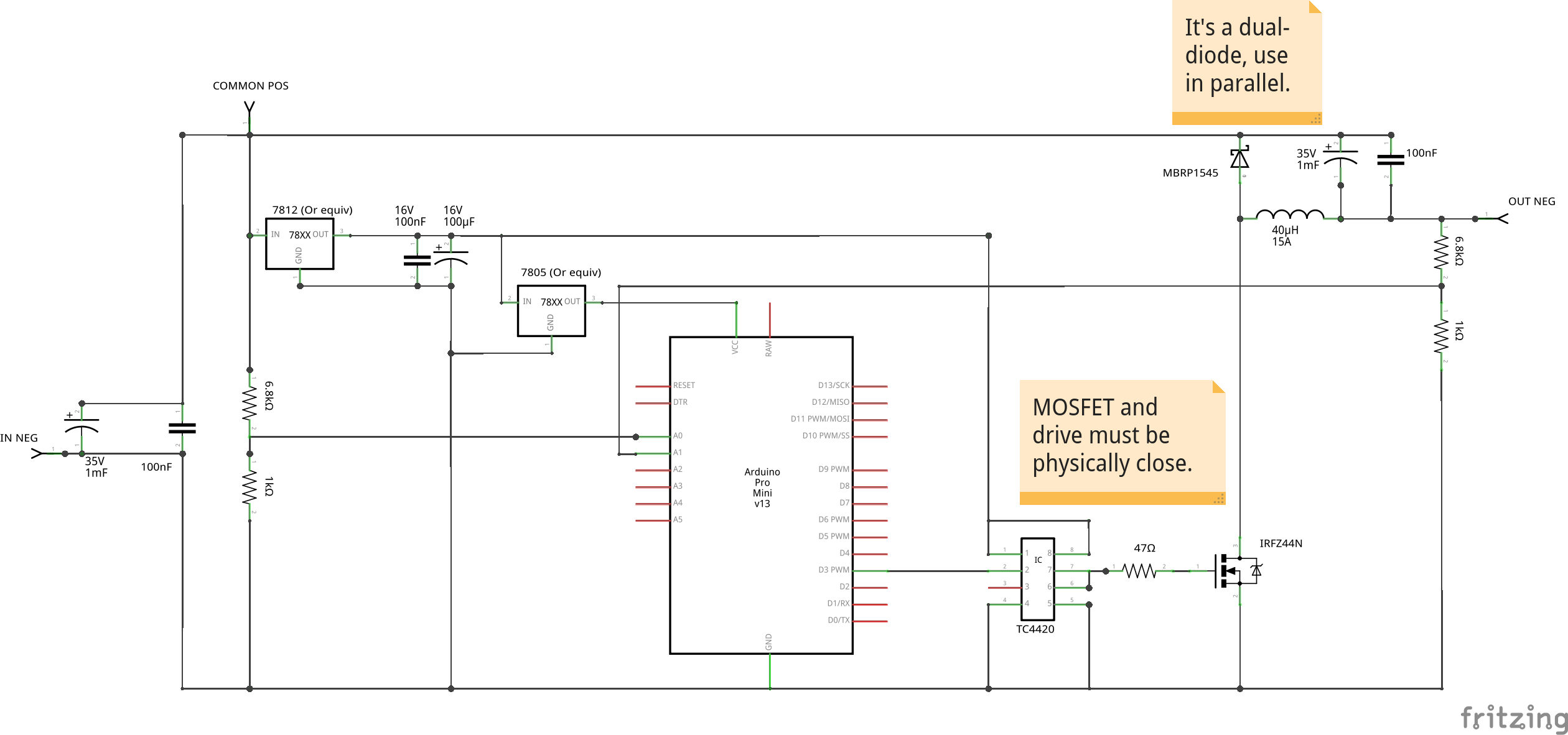
The most essential element of the circuit is a buck converter. This is almost a textbook design, with one critical modification: The switching element is on the negative side. This allows the use of an N-channel MOSFET. As N-channel MOSFETs can have lower on-resistance than P-channel, this can improve both efficiency and maximum power capability. I determined experimentally that an inductor value of 33-40uH is suitable for a 100W panel - my prototype used a Coilcraft SER2918H-333KL. The main concern in inductor choice is low resistance and ability to handle peak current (Which is greater than average output current!) without saturating - but as buck converter design is a well-studied subject, I will not go into great detail on this subject. Suffice to say that I can only promise the components specified here will work for a 100W panel: Any more current than that, you may have to revise the choice of inductor.
In experimental testing, going from a 15V input to a 12V output (a reasonable estimate of likely conditions for battery charging) I measured an efficiency of 94%. I have not determined the maximum power handling ability, but under a 100W load and using only small heatsinks the MOSFET and diode were barely warm to the touch. I could not test under higher loads simply because I lack a power supply capable of sufficient power output at the required voltage. I believe the limiting factor will be inductor saturation.
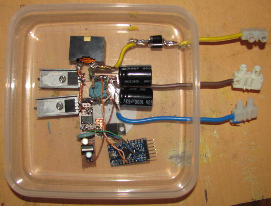
Due to the high current, it may be more practical to assemble this part of the circuit by simply soldering components directly together rather than using a circuit board. This is the manner in which I assembled my prototype.
The PWM signal for the MOSFET comes from an arduino microcontroler, for ease of prototyping and hobbyist building. Although MOSFETs with a low enough threshhold to be driven from 5V logic are readily available, the arduino is not capable of driving the gate at the required frequency and acceptable transition times directly. For this reason, a MOSFET driver is required. A TC4420 is ideal.
Early prototypes had problems with extreme ringing and induced voltage on the gate. Avoiding this problem requires two measures be taken: First, the physical distance between drive and MOSFET must be minimised to keep inductance low, and likewise the driver must be near to the smoothing capacitors on the 7812 output or else have its own decoupling capacitor. Secondly, a resistor (experiments found 47Ω optimal) in series with the gate keeps ringing to an acceptable level even at 200 or 250KHz.
A basic 7812 voltage regulator supplies power to this driver, with appropriate filtering. A 7805 is in turn cascaded from this to power the arduino. There is no reason these could not be replaced with more efficient components - I used 78xx only as they are readily available and very low cost. This double-regulator approach serves two purposes: To better isolate the arduino from any switching noise, and to prevent it from turning on until the panel is producing sufficient voltage to drive the MOSFET and driver. Note that the arduino includes its own decoupling capacitors and brownout management.
If the load is a battery, it is possible for the battery to discharge via the MOSFET body diode and solar panel at night. This is a problem whenever solar power is used to charge a battery, and is most commonly avoided by the use of a schottky blocking diode, at the expense of a small portion of the collected power. A typical diode with a 0.4V drop connected before a 13V battery, as is typically fitted inside any off-the-shelf PWM charge controller, will consume 0.4/13=3% of the panel power. However, if connected to the input stage of this optimiser and so to the typical 16V of a panel at optimal voltage, it will consume only 0.4/16=2.5%. If this is still too much, an 'ideal diode' is also an option - a circuit that uses an actively switched MOSFET to emulate a zero-drop diode. If the load is not a battery at all, but a directly powered device, then the diode can be omitted entirely.
Two voltage dividers allow the arduino to monitor both input and output voltage. Input voltage monitoring is not strictly required for optimisation, but measurement is required in order to calculate the output voltage due to the common-positive topology. Input voltage monitoring is also used to prevent the input voltage from being pulled low enough that the active electronics cannot function. A significant missing element is current monitoring on the output: This would require a number of additional and more specialised and thus expensive components, and a reasonable degree of optimisation is possible even without that information. Note that the output voltage measurement is 'backwards' because the circuit uses a common positive, and the true output voltage is obtained by subtracting the measured output voltage from the measured input voltage.
Note that the 6.8k resistor is not just part of a divider: In the event that the voltage on the output is below that on the input (perhaps due to installation error), it also limits current through the arduino input protection diode to prevent damage.
In order to further reduce component count, no filtering capacitors are used on the voltage sense inputs - removal of high-frequency noise is instead performed in software, by averaging multiple samples.
The algorithm used is a very simple form of hill-climbing: The PWM duty cycle is slowly increased or decreased, while monitoring change in the output voltage. If the voltage decreases, the direction is reversed. The duty cycle will also never increase if doing so would pull the input voltage below seven volts, as operating under low voltage conditions may prevent full turn-on of the MOSFET. The rate of change of duty cycle is proportional to the rate of change of output voltage, clamped to a value low enough to avoid chaotic behavior.
Though unsophisticated, the algorithm shows promise - and it is not difficult to test potential refinements. One issue is that it could be easily thrown off by a load that doesn't draw a steady current without sufficient filtering between optimiser output and load, and if multiple optimisers are connected together in series or in parallel they could potentially interact in unpredictable ways. Such issues will require a larger-scale, multi-panel test environment to explore. The measurement of output voltage rather than power also assumes a load for which current increases with voltage - this is true of batteries under direct connection and most other loads, but again strange interactions may occur with PWM chargers or switching power supplies - loads for which this assumption does not hold.
This algorithm is based upon that used by Julian Illet on his 'MuPPeT' MPPT charge controller, with some very minor refinements.
I initially experimented with an approach regulating for a constant panel voltage, and applying P&O to the target. I found this to be very unstable under most conditions, while the ramp-and-direction approach performed much more predictably.
There are few practical problems in the software design. It does require some careful use of the arduino PWM functionality. In order to get a sufficiently high PWM frequency from the arduino it is necessary to lower the 'top' value for the PWM generator, sacrificing accuracy for frequency. Other than this it's just a very simple program.
The code is open as MPPT_Direct.ino, do as you wish with it. This version will write voltage readings and PWM to the serial output for diagnostics and evaluation.
To verify correct operation under real-world usage conditions, a prototype was connected to a 12V, 100W (Though poorly orientated) panel on the input, and to a 130Ah lead-acid battery in a state of partial discharge via diode on the output. The current into the battery was measured under this configuration, then measured again after linking the solar and battery terminals of the optimiser to bypass it. This procedure was repeated five times over the course of a morning, as the sun rose and panel output varied.
| With optimiser | Bypassed | Power gained |
| 1.00A | 0.85A | 17% |
| 0.75A | 0.69A | 8% |
| 3.83A | 3.41A | 12% |
| 3.70A | 3.30A | 12% |
| 4.06A | 3.60A | 12% |
This conclusively shows that the device does work, and that it provides an increase in harvested power of approximately twelve percent under test conditions. This is approximately in line with the earlier estimate: If the panel was operating at 81% (very roughly) without the optimiser, and the optimiser increases current by 12%, this corresponds to a new efficiency of 90%. Within what might be reasonably expected.
The simple algorithm used, though effective on simple resistive loads, may result in erratic behavior when unloaded or underload.
Incorporation of an ideal diode circuit may result in a usable output increase of up to 6%. This could also be combined with monitoring of output current and thus true power. An INA219 may be suitable.
The tracking algorithm is dependant upon the load drawing a reasonably steady current. It may be unstable - or even form a chaotic system in conjunction with - certain load devices, including some PWM charge controllers. It may be possible to fix this by using additional filtering.
It may be possible to use multiple optimisers in series or in parallel - but the present design is not tested in this configuration, and chaotic interactions are a distinct possibility.
The 7812-to-7805 regulator power supply is inefficient - replacement with a switching 5V supply module or low-quiescent-current linear will slightly reduce current, but not by a significant amount. I did not judge this saving of a few milliamps justified the additional expense.
Adding a second MOSFET and suitable driver for syncronous operation might raise efficiency a few more percent.
Circuit and development by Codebird, https://birds-are-nice.me/