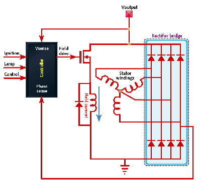
David Swanson's design, simplified schematic.
In the field of hobbyist electrical generation, it is common to repurpose alternators from cars or other vehicles. These may, with enough gearing and mechanical skill, be driven off of a smaller engine, wind turbine, water wheel or turbine, methane engine, pedal bicycle, or many other sources of motive power. As useful as these alternators are, they are still designed for a vehicle, and this limits their adaptability. To aid in this I describe here an open design for a field current voltage regulator. This device is simple to construct and may be retrofitted to most vehicle alternators, replacing the existing voltage regulator electronics. This makes it easy to set the desired output voltage, or increase the field coil current to allow the alternator to run at a lower rate of rotation. It also utilises an improved 'freewheel' field coil drive that can substantially reduce the power consumption for the field coils.
The alternators used in automotive applications, in almost all cases, follow a common design: Power is generated on the stator (usually via six coils in a three-phase arrangement), then rectified into DC. The required rotating magnetic field is generated by a field coil located on the rotor, supplied with DC via by slip rings. This arrangement means that the slip rings do not need to carry the full output current, only the far lower current for the field coils. These alternators always incorporate a voltage regulator circuit, either internally or as a replaceable connected module, which monitors the rectified output voltage and regulates the field coil current and thus field strength to maintain the target output voltage as load current and rotational speed vary. This regulator is often mounted on a carrier along with the brushes, for easy replacement.
A small mechanical aside: The electromagnetic elements of alternators are such that they will work equally well when rotated in either direction. It does not matter, and at low current output direction can be safely ignored. However, most alternators do include a cooling fan which is designed to work only in one direction of rotation. If drawing high current while turning the alternator 'backwards' this reduced cooling efficiency may lead to overheating.
These regulators are designed for using the alternator in its intended application only: To maintain battery charge in a car or other vehicle. For this purpose they perform very well, but if these alternators are repurposed for an application other than the intended such as a home-built hydro-electric generator, wind turbine or other alternative energy machine then the limitations of this regulator become more of a concern. Specifically:
There is an alternative, which avoids the worst of these limitations: You can build your own microcontroller voltage regulator. It requires a minimum of parts - a conventional voltage regulator, a small arduino pro mini or nano 5V, a MOSFET, and a few passive parts. This design is easy to construct and can be retrofit to most car alternators by just cutting the connections on the existing regulator and soldering wires to connect in its place. As well as allowing older alternators to better perform in unconventional applications, it might also be fitted to very new alternators which include integrated microcontroller regulators that will not operate without a connected engine control unit.
This design is based in part upon a partial design published on embedded.com. This text is intended as a guide to the practical implementation of a simplified variation of this design in a hobbyist-friendly way for use in applications other than vehicles. The simplifications (specifically removal of the offset amplifier and phase sense) do mean that the ripple voltage will be greater, but this can be reduced using a simple smoothing capacitor of sufficiently large value or pi filter.
David Swanson's design, simplified schematic.
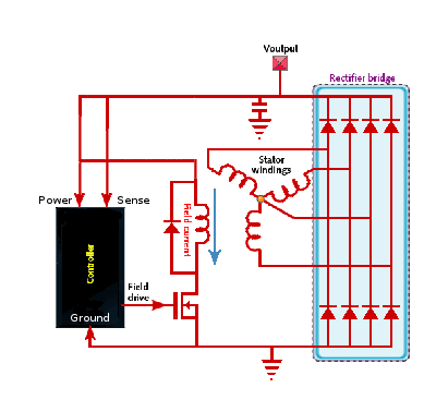
My alternative design, simplified schematic.
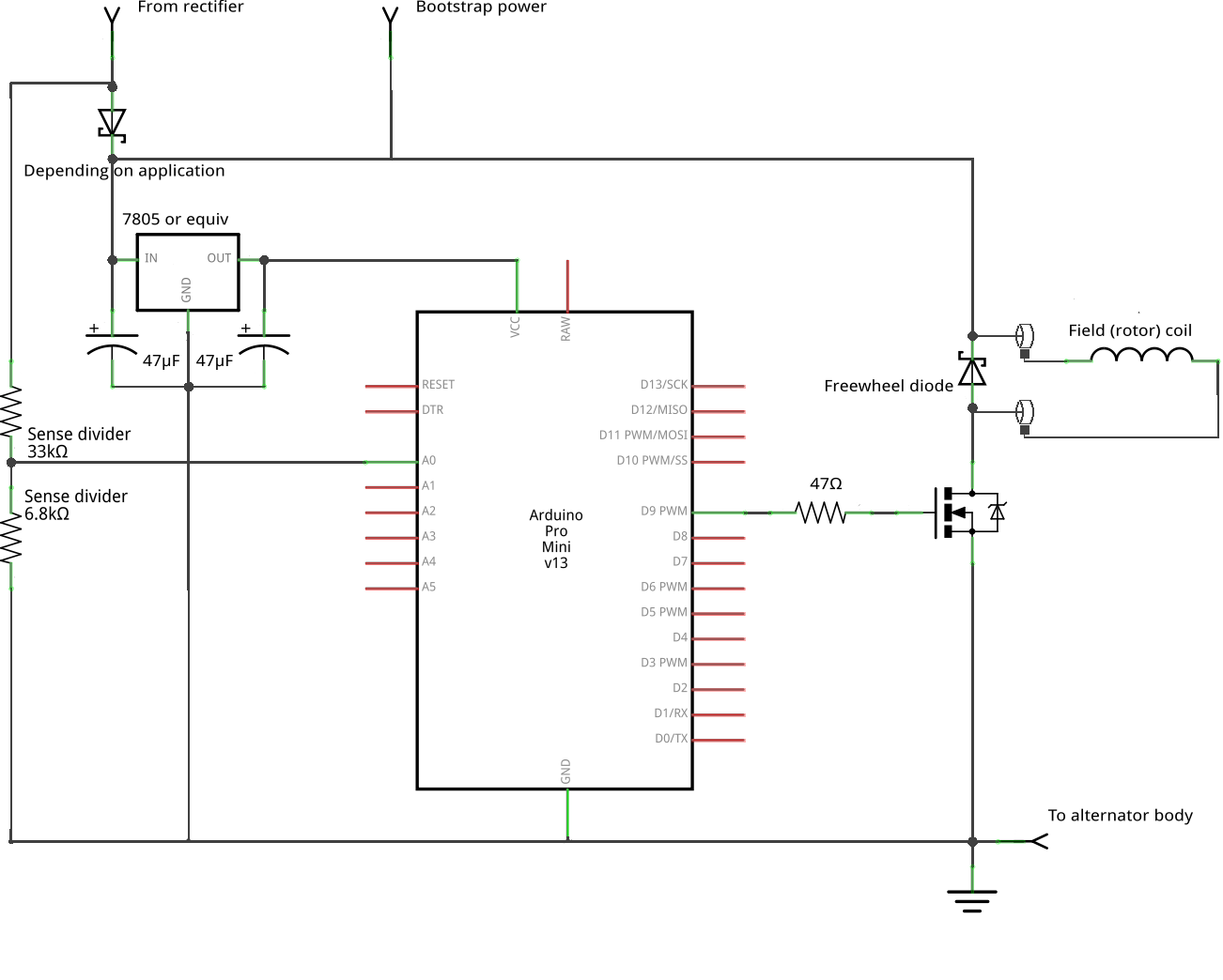
The MOSFET must by selected carefully. There are two critical factors. Firstly, it have a threshold voltage below 5V to allow the arduino to operate it directly. Secondly, it must have a max Vds rating far in excess of the intended output voltage. This is essential to avoid a potential catastrophic failure mode. In the event of a sudden drop in load current, the alternator output voltage may briefly experience a very substantial voltage spike before the rotor field strength can fall to compensate. If this spike exceeds the transistor max Vds it will cause the transistor to conduct in avalanche breakdown, which will in turn create a high current in the field winding, strengthening the field, driving up the rectified voltage, further increasing field current... this positive feedback cycle would continue until either the mechanical power source is insufficient or the field windings fail. This could destroy the load alternator or the load, or strip teeth from gears in an engine. To guard against this possibility it is essential that the power MOSFET be able to withstand such a voltage spike - ten times the maximum intended output voltage is a good guideline. The use of a fuse in series with it is also a good idea.
The prototype used in development utilised an IRF3205 power MOSFET. This component is suitable only for very low-power operation as it's maximum Vdss is only 55V, not sufficient to protect against a worst-case surge and avalanche current feedback loop. The IRF520 may be a suitable component.
Another person who contacted me regarding their own implimentation of this circuit found that the 5V from the arduino was not sufficiently to fully turn on the IRF3205 - though it is above the threshhold voltage, it is not far above it. I did not encounter this problem myself, and believe it may be due to in-tolerance component variation: The IRF3205 is specified for Vgs(th) of 2.0-4.0V, easily enough to affect the operation of the circuit. Because of this it may be nessicary to revise the design to include a simple one- or two-transistor gate driver.
The freewheel diode should be Schottky type, rated for at least the highest expected field coil current - for most alternators this will be no more than three amps. The existing three-phase rectifier circuit built into the alternator is still utilised. The diode shown before the 7805 is not required for all configurations - for details see the section on bootstrap power below.
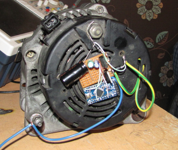
The crude prototype used in development, fitted to a Bosch 70A alternator. This alternator has a 38mH field winding. Yes, mH - think how big it is.
The Swanson design aims to achieve a target output voltage regulation of ±200mV without the use of a large smoothing capacitor. To do this requires the use of an offset amplifier. This is a practical solution, and requires only a single IC and a few passive components, but if regulation requirements are slightly relaxed this part of the circuit can be eliminated.
For a 14V output alternator, the maximum voltage to be measured can be estimated at 25V - the 11V margin is an allowance for voltage surges. resulting from a sudden drop in load current if a consuming device is switched off or a fault occurs elsewhere. A very large surge could go over this, but if so it will just saturate the ADC and run to ground through the ATMega input protection diode. With an ATMega ADC of 10-bit resolution and 0-5V range, this requires a divider of 0.2, or ratio 4:1, and gives a final resolution of 0.02V. This is enough for ±100mV regulation under conditions of constant load, but it must be accepted that the output voltage will not be so stable under rapidly varying load: This is the cost of simplified design. Greater stability is only going to be possible by using external filtering or regulation.
The choice of divider ratio is determined by desired output voltage. Regardless of ratio used, a constant in the source file must be configured appropriately for it. If not using high-precision resistors, compensation for manufacturing variation can also be performed with this constant.
Note that the precision of the output (though not noise level), and temperature-dependence, does depend upon the choice of voltage regulator for the arduino. The common 7805 and its low-current counterpart the 78L05 both range from 4.8 to 5.2V, which may not be sufficiently accurate to directly charge a lead-acid battery. This can be fixed by either using a higher-precision voltage regulator (possibly an LM1085), or adding a reference voltage from a precision zener or reference chip to another analog input to allow compensation in measurement. The L4995 may also be suitable, and includes a built-in watchdog timer, but has the notable drawback of being available only in surface-mount form.
A notable improvement in this variation upon the Swanson design is in the manner in which the freewheel diode is used: While the Swanson design uses it only to divert back EMF from the coil, it can also be repurposed to increase efficiency. The field coil is not merely an inductive load: It is a very inductive load, an electromagnet formed on an iron core. A typical alternator might have 30mH inductance. At a sufficiently high PWM frequency, the current flow through the field coil continues even in the off-stage of PWM, circling via the freewheel diode. This mode of operation is very similar in nature to a buck converter, and offers the potential for substantial reduction in energy usage - in experimental testing a field coil current three times the draw on the power supply is easily achieved at low PWM duty cycle. Don't expect miracles from it though: The field coils do not have a laminated core, so cannot run at a high frequency. The arduino default of 490Hz, surprisingly, actually works. 1KHz also works, and gives slightly improved performance. A downside to this is that the field coil becomes a potent source of magnetic noise to all nearby electronics, so you may have EMI issues.
As effective as this approach is in reducing power consumption, it does complicate the matter of controlling the field current without the use of a current sensor of some description that would complicate the design. Fortunately, though the underlying mathematics are complicated, the final behavior is not: Over most of the PWM duty cycle range, mean field current is approximately determined by a simple formula: I=K*V*D, where K is a constant depending upon frequency and field coil characteristics, V is the supply voltage and D the duty cycle. As V is known, it is simple to determine a D such that I remains reasonably constant as V varies. This is only a very approximate model, but any deviation from it is handled easily by the feedback control algorithm - the only requirement is that I is an increasing function of D under constant V, which is always true.
It is only necessary to make one adjustment to the code that is specific to a certain model of alternator: 'const float maxPVP' must be determined experimentally. It determines the maximum allowed product of V and D, and so limits the maximum current that will be passed through the field coil. A higher value will allow the alternator to operate at lower speed (and higher torque), but at the expense of higher field coil power use. Too high may lead to overheating, especially if the alternator is not spinning at all and so is without airflow from the internal fan.
When measuring field coil current to determine a suitable value of maxPVP, it may be useful to use an old analog multimeter. Some DMMs will have difficulty measuring a current under low-frequency PWM.
The microcontroller must monitor output voltage and possibly field current, and adjust output PWM using a model of their relationship. This task is not overly difficult under steady state conditions, but is greatly complicated by the presence of noise from various sources and by the delayed response to PWM duty cycle changes which can easily lead to oscillatory behavior.
A serious concern is that a sudden drop in load current - such as a device being turned off - could cause the alternator voltage to rise far above the safe level before the microcontroller is able to react. At worst this could lead to the catastrophic feedback loop described above - to minimise the possibility of this happening, the microcontroller must react rapidly to over-voltage condition.
Another serious concern is that the algorithm may over-react to noise, interacting with in unpredictable, chaotic ways or straining the mechanical components with sudden changes in load. Clearly some careful consideration and filtering is needed, as well as a sizeable (At least 1000μF) smoothing capacitor on the rectifier output.
The Swanson design has a very effective method of eliminating the alternator output fluctuation: Sample the voltage in phase with the rotor rotation, sensed from one of the stator coils. This is simple and effective, but unfortunately not an option here as it cannot be retrofit to an existing alternator: The individual stator coil terminals are often buried deep inside, and the rectifier inaccessible behind a protective plate. Instead a cruder method of low pass filtering may be used.
Synchronous sampling can be used instead to eliminate any noise from the PWM signal itself. With a little creative use of the ATMega 'timer1' it can be used to generate a high-precision ten-bit PWM signal while also calling an interrupt on each cycle. Placing the ADC call and feedback calculation in this interrupt and setting prescaling for a 1KHz PWM frequency gives one millisecond to complete these calculations, and running the PWM output, sampling and calculations in lock-step avoids any issues relating drifting synchronisation and beat frequency noise.
The feedback algorithm itself presents some difficulty, because the alternator acts as a delay: A change in the PWM duty cycle will take a number of milliseconds for the field to adjust to the new value, which leads to an equal delay on the output voltage. Any negative feedback control system which includes a delay can be susceptible to oscillations. During early testing this proved to be a problem - it took many attempts and several blown test-load bulbs to come up with a stable, fast, oscillation-free algorithm utilising two separate but connected control loops.
The first of these is responsible for rapid-response control of the field current: It simply takes the difference between the measured voltage and a target value, divides by a constant 2 (found by trial and error to work well), adds 0.5 and clamps the result in the range 0-1. Simple, fast, but with the limitation that although it will maintain a constant voltage it does not determine what that voltage will actually be.
The second control loop adjusts the target of the first loop to maintain an output voltage in accordance with the desired output. It serves to better compensate for non-linearities in the relationship between PWM duty cycle and output voltage.
The output of these is a value from 0-1. This does not determine the output PWM directly: It determines the proportion of the maximum field current which will be applied while compensating for variation in the supply voltage. This current is determined by a combination of the configuration constant maxPVP and the electrical properties of the field coil. Such an approach allows for the alternator to operate over a very wide RPM range, and is integral to the low-power idle mode. It does require that the bootstrap voltage be known when programming the microcontroller, if operated in a configuration in which bootstrap power is used.
Alternators using electromagnet field coils consume a small amount of electrical power to create a larger amount of electrical power. This is intrinsic to their design, and controlling this process is the purpose of the voltage regulator. Though it can produce large amounts of power with high efficiency, this does present two drawbacks:
To address the first of these, the design can be fed bootstrap power in multiple ways depending upon the presence or absence of diodes in key locations. This needs minimal software change, but the bootstrap voltage must be specified in order to properly calculate field coil current. The bootstrap voltage must be at least 5-7 volts, depending upon the voltage regulator used to power the arduino.
With no diodes, it functions like a conventional automotive alternator: Drawing power from a battery to start, then charging it. This configuration is the simplest, but it has some downsides. As the voltage divider can only measure battery voltage, not the output of the rectifier in isolation, it is not possible to use the automatic low-power mode feature. Another means is required to disconnect the field coils and/or controller when not in use, or the battery will be drained.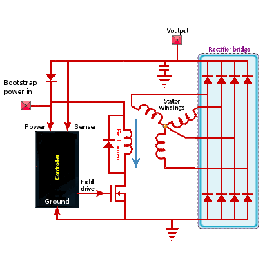 A diode before the power to the regulator and field coils allows for the use of an external 'bootstrap' power source. This mode is suitable for powering a load that does not have energy storage ability - the bootstrap power need be as little as 7V, 0.5A -less if using an LDO regulator. Such a small supply can be easily generated by a small solar panel, battery, permanent magnet alternator or even hand-crank generator. Once sufficient speed is achieved, the alternator becomes self-powering. You will still need some form of energy storage on the output to ensure stable operation, such as a capacitor or supercapacitor bank. As the voltage divider cannot monitor bootstrap voltage, this must be fixed and configured into the firmware.
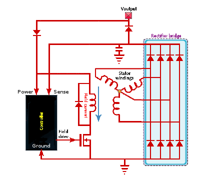 Two diodes in combination - one from rectifier to output, and one from output to field coil and regulator supply - also powers the alternator off of a battery that it subsequently charges, much like the first mode. This configuration does have an advantage: It allows the automatic low-power mode to function. There will be a diode drop which must be allowed for, or an active 'ideal diode' circuit can be used. Again, the bootstrap voltage must be regulated and configured. Note also that this mode will result in a slightly lower field coil current due to the diode drop, but this can be compensated for in software easily.
The firmware provides two further means of minimising inactive power use. The first of these is an 'inhibit' input, on digital input pin 8 with the internal pull-up enabled. If this input is pulled low it will cause the field coils to be shut down, reducing power usage to no more than that of the microcontroller itself. This operation can be easily inverted by altering the code. This input can be connected to a switch, a relay on an engine ignition circuit or a rotation sensor. It could also be modified to require a periodic signal to enable, for use with an optical or magnetic rotation sensor.
The second feature is a 'low power' mode, which is entered whenever the output voltage is less than 0.25 of the target, and limits the field current to 0.25 the maximum. With the alternator used in testing current consumption is only 70mA when not spinning - a figure that does not vary very much with bootstrap voltage.
Between the schematics above, this description and the source code for an Arduino, all the information required to construct this regulator is here. The code will require some minor adjustments for any specific model of alternator. Do not depend upon voltage regulation being entirely stable under rapidly-varying loads unless you also have a supercapacitor bank or lead-acid battery in parallel.
This design can be used for bulk charging of a lead-acid battery, but it supports only fixed-voltage output regulation. It cannot be used for long-term float charging of such a battery without compromising battery life due to a lack of temperature compensation. If this feature is needed, it could be added using either a thermistor voltage divider on one of the unused analog inputs or a DS18B20 digital temperature sensor.
This design has not undergone strict testing. It has been evaluated in charging of a lead-acid battery, during which it was able to sustain a regulated output voltage of 13.6V with a stability of ±50mV, at a current of two amps. This is far below the alternator's rated current capability, but all that could be achieved under equipment and budget constraints. It did achieve this stability under a very variable speed of rotation, as a pedal bicycle was used as the motive source - though if you want a stable output, the use of a flywheel is advised. Performance on a varying load has not been assessed, but is certain to be far worse.
This design is not capable of precise voltage regulation - and no PWM-driven alternator controller can be. It's fundamental limitation of the approach: PWM frequencies much greater than 1KHz lead to unacceptable eddy current and hysteresis losses and EMI emissions, but such low frequencies will inevitably impose some noise on the output. Under ideal conditions, the test-alternator was able to get ripple voltage when charging a battery down to ±50mv - but a load drawing rapidly varying current might see voltage variations up to a volt, as the 1KHz control loop cannot compensate fast enough. In order to provide greater stability an external filter is needed. In the original automotive application, the battery serves as this filter and permits the vehicle's main power rail to remain, if not entirely noise-free, at least close enough that simple regulators and LC filters on sensitive electronics can render it usable. In other applications, if an exact and stable output is required, the simplest way would be to use an external buck converter circuit and configure the alternator voltage for slightly above the buck converter output voltage. If only a noise-free output is required but precision is not required, this could be achieved using nothing but a very large smoothing capacitor.
Circuit and development by Codebird, https://birds-are-nice.me/ published 2017. This is an entirely open design: I assert no copyright upon it, and am not aware of any patents covering it. I invite any electronics enthusiast, professional or hobbyist to build a device to this design or to improve upon it. I only ask, in a polite but not legally-binding manner, that you publish any refinements.