This is a design for a light-weight dual-band antenna suitable for use on the 2M and 70cm bands in either fixed or mobile situations.
This design is based on VK2ZOI's 2M band 'flower pot' antenna and later refinement</a> of this design for dual-band operation. It is not so much based upon as directly copied from: Electrically, they are absolutely identical. The refinements that I describe here are of a purely mechanical nature. By incorporating an element of 3D printing it is possible to greatly reduce the size and the weight of the antenna.
This refinement comes with the obvious advantage of mobility, and one less obvious: You can roof mount it without access to the roof. It's slender enough that I was able to install it by drilling a hole into the apex of the roof from underneath, within the loft. The slender antenna may then be pushed through the hole. A little sealant to prevent rain getting in and you have an antenna just above roof height, free of any obstruction from the roof structure, without any need to deal with working at heights.
VK2ZOI's 2M 'flower pot' antenna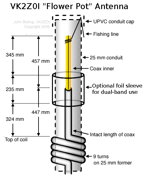
Electrically, this is an end-fed dipole, counter-intuitive as that may sound. The key to understanding it is to recognise that there are two completely independent currents flowing in the lower half of the antenna: One is the feed line current, the other the antenna current, and despite sharing conductors they do not interact at all.
It may help to visualise this as the feed line flowing on the inside of the coax, and the antenna on the outside. This isn't really an accurate description, but helpful in visualisation.
While the far end of the dipole is terminated in the conventional manner by simply cutting the wire, this isn't possible for the near end as the coax serves this dual function. Instead it is terminated with a common mode choke: Nothing but a coil of coax. The balanced current of the feed line passes through (and the choke, acting as a balun, makes sure it is balanced), while the unbalanced radiating current is blocked.
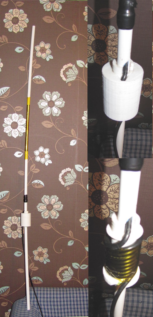
It works very well, so long as you use a good quality coax. RG58 is a good choice, as it's thin enough to wind easily. As an added bonus, the terminating choke coil also acts as a balun and helps with impedence matching.
One downside is in tuning - while VK2ZOI's dimensions are close, the need for manual tuning after construction is unavoidable, and the plastic enclosing pipe alters the velocity factor enough that if the antenna is tuned without that enclosure it will be out of tune when enclosed. The dimensions of the enclosure, type of plastic and type of braid on the coax will all affect the frequency. You will need an antenna analyser or an SWR meter suitable for use at VHF/UHF frequencies, and some trial-end-error trimming.
While RG58 is good for making the antenna, if using it as a roof mount you may want to use something lower loss like RG213 for your feed line - RG58 has high loss at 430MHz.
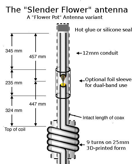
I name my revision the 'slender flower' antenna, and it differs from VK2ZOI's design in three ways:
The 3D-printed coil form I designed has two parts: The form and the lid. Their assembly is readily apparent. Both are easy prints with only slight overhang on the form and none on the lid.
The antenna is very easily disassembled for adjustment: Measure, pull cable, trim cable, reassemble. If you need more cable you can just slide it through the choke coil.
My own antenna uses kapton tape to hold the foil shield - the low coefficient of friction is ideal for sliding through a hole drilled in the roof, making it usable as a roof-mount antenna without any need to get a ladder to the roof in order to fit it. A bit of electrical tape serves as a 'plug' for the hole to keep water out, and an empty extension of the 12mm conduit is used both for anchoring to a convenient beam when fitted on the roof and as a handle when taking it down to go mobile.