Ever wanted a simple circuit to turn something off if you leave it on? That's what this does. It sits in front of a device to be powered (if that device runs on 12V DC), and if power remains on for more than a set time it will turn the device off. Just turn power off and on again to reset. It's handy as a precaution against leaving the lights or an ornament turned on and wasting power. I used it to ensure some solar-powered garden lights were not left turned on.
There are a few of these circuits around, but I don't think you'll get one with a lower part count than this. It's adapted from one I found on reuk.co.uk, but I revised it to reduce power consumption and part count. The relay is gone, replaced with a MOSFET that is more durable and more efficient. The oscilator I use is slightly different too, but I've tested it and found it works nicely.
Though these days, it's probably more practical to program an eight-pin microcontroller of some description. Cheating.
Original inspiration circuit.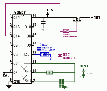
The part values on the schematic will give a delay of slightly over four hours, but you can modify this easily enough. The delay is proportional to the timing resistor, and inversely proportional to the timing capacitor. To calibrate, check the test point on pin 7: The time before turn-off will be exactly 512 times the period of the output on this pin. You can change this ratio to 256 or 128 by swapping the wire from pin 3 to pin 2 or 1 respectively. This is an RC oscilator, so it's not going to be high precision. I found that at the really low frequencies used here, there was no need for a resistor on pin 11 as the datasheet suggests.
The timing capacitor should be 50μF, non-polarised, for the four-hour delay. This is a unusual part, rather expensive, but there's a workaround: The 'poor man's capacitor.' If you take two electrolytics and connect their negative sides together, they can be used as a non-polarised capacitor of half(ish) their value: Two 100μF electrolytics make one 50μF non-polarised. It's a terrible capacitor. The ESI and ESR of such an arrangement is awful, and it'll probably burst like popcorn if you try to handle any significent amount of current. For an application as undemanding at this though, it will work perfectly. Really, you're probably better off with a 330KΩ resistor and 5μF capacitor - I just used these values because I happened to have a big bag of 33KΩ resistors. That's also why I used a 33KΩ for the MOSFET gate - you can probably do without this on most MOSFETs, but better safe than sorry.
I built this to turn off some garden lights after four hours, so they won't bother the neighbours by being left on all night. It's a useful little circuit to make sure you won't drain your batteries dry if you forget to turn something off. It will operate on a voltage from 5V to 20V, assuming you use the high-voltage varient of 4060B: Careful of the M74HC4060B1, as it has a 7V maximum supply. The CD4060B or HCC4060B will run on 20V, which is also the max Vgs on most MOSFETS, or use an HCF4060B which has a maximum supply of 18V. For the MOSFET I used an F9450N, but most P-channel power MOSFETs will work. If you want to switch on the low side with an N-channel instead, just use a simple inverter like a BS170 with a pull-up resistor.
The workings of the circuit are fairly simple: The 4060B combines an oscilator (which can be RC or crystal) with a frequency divider. This circuit uses an RC oscilator running at a very low frequency, which is in turn divided over fourteen stages to finally give a signal with a period of nearly nine hours - or would, if it managed a full cycle. After a half-cycle the output finally turns high, which both turns off the load device via P-channel MOSFET and inhibits the operation of the RC oscilator via a diode, ensuring the load then remains off until power is disconnected to reset the circuit.
There's a filter cap between power and ground pins on the chip, as per standard practice. It's there to prevent high-frequency noise on the input from causing unwanted mis-counting. You can use pretty much any ceramic capacitor you want there, exact value unimportant.
The final element is the turn-on reset circuit. While some counter chips can guarantee starting a count at zero on power on, the 4060B is not one of them: The initial state of the flip-flops is indeterminate. To fix this the reset pin needs to be held high for an instant - a few miliseconds will do - after power is applied. There is no limit on transition time, so a simple RC delay suffices. I've roughly calculated and tested that a 100nF capacitor and 33KΩ resistor will work with a comfortable error margin, but you can change these so long as the product of the two values is at least equivilant to that. A 10nF and 300KΩ will work the same, or a 3nF and 1MΩ.