
Project write-up: 3D-printed and scrap wind turbine.
The objective of this turbine is not to generate power, but to assess the performance of certain component and design elements relating to low-cost turbine construction using salvaged or 3D printed components. The turbine is also documented on thingiverse and four videos (1, 2, 3, 4).
The project was partially successful. Though blades, sliprings and most mechanical aspects performed well, a poor choice of generator crippled power output to no more than one watt. These notes are released to allow others to refine the design and solve this problem.
Blades:
The turbine uses a set of six 'Power Plus' hobby wind turbine blades purchased from the eBay seller Windysolar. These were chosen for their very low cost and simple construction - they are no more than sheet metal cut into shape and bent into a curve. Though they may not have the efficiency of a more carefully aerodynamically-designed blade they are far cheaper. They also have the advantage of robustness: If damaged they can be easily bent and hammered back into shape without impairing performance.
Due to their poor lift-drag ratio these blades perform best with a six-blade design, sacrificing speed for greater toque. Though they may appear crude, these blades are surprisingly capable in both speed and torque
A set of three smaller, sharp-bend blades from Windysolar were also tested, but their performance was poor - they produced very little torque, and Windysolar has now switched from these blades to the superior 'Power Plus' design for pre-built turbines.
Turbine body:
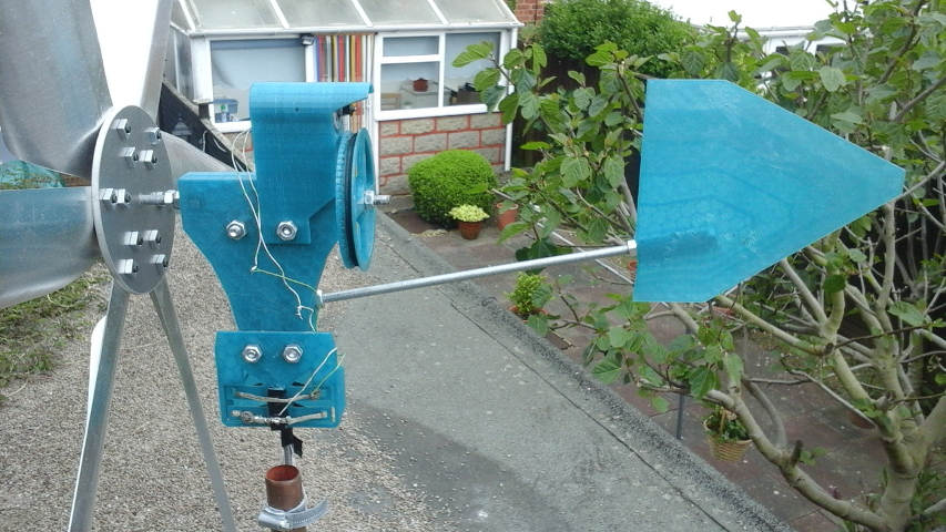
The turbine body is manufactured from two clamshell 3D printed sections and four bearings. It serves to support the main shaft, tail, slip rings and motor mount.
Body STL, print one normal and one mirrored.
Tail:
The tail is 3D printed, and attached to the turbine body via a 3D printed bracket and threaded rod. The bracket also forms the rain shield for the slip rings.
Transmission:
A typical hobby wind turbine uses a direct-drive construction, in which the blades connect directly to the alternator shaft. This design is mechanically efficient and easily constructed, but requires an alternator capable of performing efficiently at very low RPM - these components are difficult to obtain, leading many hobbyists to construct their own alternators. As an alternative this turbine uses a gear or belt drive to run the alternator at far greater speed than the blades turn. The transmission is at the rear of the turbine and can be easily adjusted without disassembly.
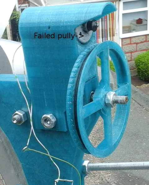
Both gear and belt transmissions were tried. Gears were found to be noisier but more reliable. The very high rotational speeds combined with variable temperature conditions outdoors were demanding on the belts, leading to several belt and even pully failures before a durable enough belt could be found. The extruder gearing from a K8200 3D printer was found to be well-suited for the task.
Pully at thingiverse, STL.
Generator:
The transmission allows more flexibility in choice of generator than a direct-drive turbine, but selection of a suitable component remains essential. The DC motor chosen for this turbine was not appropriate, and limits practical power output to approximately one watt. Though all DC motors are capable of running as dynamos, their design is not optimal for this purpose - the magnetic field strength is typically too low, and multiple windings may be connected at different phase offsets leading to power loss and reduced voltage output under load. A better choice of motor would have improved power output greatly.
An interesting aspect of the DC motor used is that outut voltage self-regulates under load, never rising above three volts - increasing RPM allows for a greater current to be drawn without the voltage dropping, and increases open-circuit voltage, but this open circuit voltage drops rapidly when current is flowing. This appears to be a consequence of the commutator connecting two coils at once in order to provide a more steady torque when used as a motor. This strange self-regulating property occurs even when driving a simple resistive test load.
Other hobbyists have reported success using directly-driven stepper motors, but these require considerable torque to overcome cogging. Some brands of larger DC motor have also been reported successful - Windysolar suggests using motors intended for treadmills. The Green Energy Blog has further suggestions on motor selection, including rewiring brushless DC motors to function as alternators.

Slip rings:
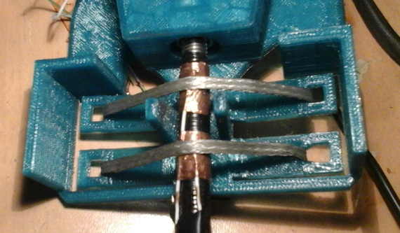
The slip rings are formed around the support pole. This is wrapped in insulating tape, then two bands of copper tape. A 3D printed bracket attached to the turbine body holds two sections of braided earthing strip against these, forming a good electrical contact. A second 3D printed section acts as a rain guard.
While copper is subject to corrosion, the rotating motion of the earthing braid may also act as a self-cleaning abrasive to keep the copper exposed. The durability of this form of slip ring under weathering has not yet been assessed. A copper desoldering braid may be a superior material for the contact as it would reduce any potential electrolytic corrosion problems.
STL.

Electronics:
An ideal alternator or dynamo produces an output voltage approximately proportional to the angular velocity when under no load, and a drop in that voltage proportional to current. This means that the output voltage varies greatly with wind speed. The conventional approach to harnessing the electrical output of a hobby wind turbine is to combine a blocking diode and a voltage regulator to charge a battery. This works, but it is not ideal. Firstly because in low wind speeds, when the turbine is not producing enough voltage to match the battery voltage, all of the potential power it produces is wasted - no current flows. Secondly, under high wind conditions, a substantial amount of power is lost in regulation - without this regulation there would be a risk of damaging the battery though over-charging. The fundamental problem is similar to that of MPPT tracking in solar power, but far more dynamic as wind speed may fluctuate from one second to another.
An alternative approach is the use of a DC-DC converter. These are available as pre-built modules, and can efficiently step a voltage either up or down as required to a set output voltage regardless of load, if the turbine is capable of supplying enough power. This test turbine used a SEPIC converter - this can potentially greatly increase usable output from a turbine as it can charge a battery (slowly) even at low wind speeds, and allows for greater charging current at high wind speeds. A buck-boost converter may also be a suitable topology, and can be more easily constructed for high current handling than a SEPIC or Ćuk topology. Simple buck or boost converters alone are not suitable as the turbine voltage may vary both above and below the target voltage.
As DC-DC converters can act erratically when given unsteady input voltages, a smoothing capacitor is still required.
This test turbine was not connected to a battery, but directly to the load - a 10V 1W LED light array used to illuminate a garden path. The SEPIC converter was able to power this at a turbine output voltage as low as 2.5V, and maintained a steady 10V across the load regardless of wind speed.
Future aims:
I do not intend to further develop this turbine as a practical power supply due to the lack of a suitable place to mount it with good wind exposure. I do wish to assess performance of the blades when connected to a more suitable motor, and may attempt a second turbine to this end in future. My immediate interests now are towards solar panels and low-cost means of condition monitoring for lead-acid batteries.